How to install e-chains: the full breakdown engineers and assemblers actually need
In this article, we discuss the two most common horizontal assemblies/installations: both horizontal unsupported and horizontal long gliding. If you have any other configurations, such as rotary or vertical hanging, please reach out to us (1-800-965-2496 or www.igus.ca).
For both horizontal unsupported and horizontal long gliding applications, the first step is the same: assembly. If the cable carrier in question is received in sections, here’s what to do:
- Assemble the pieces to one length (pieces usually ship in meter-long sections to reduce shipping costs)
- Open the chain
- Lay the cables in place, snapping it shut
- Snap the brackets on
Once the above steps are completed, the chain is fully populated.
You may note that we have a harnessing team at our warehouse in Rhode Island, US which can assemble the cable management system for you in advance, so that only installation (the next step) is required. In addition, we can install the cable management system for you using our installation service, Orange Services.
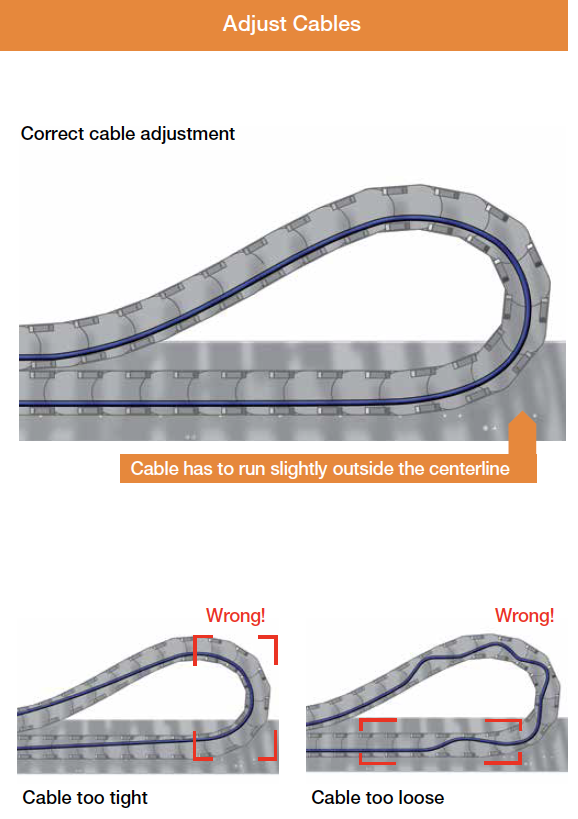
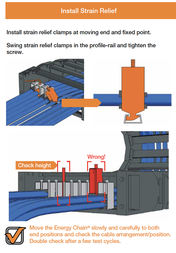
The next step after assembly is to add the strain relief to the system and then run the system a few times to ensure the cables maintain their location. Note that strain relief must be applied to both ends of the chain to prevent cables from twisting or corkscrewing. The cables must be centered, not pulled or pushed against the inner or outer radius. After running the system a few times, you can fine tune the strain relief as per the following diagram.
Whether your system is 3 feet or 100 feet, these instructions are the same. And if you have a horizontal unsupported application, this is where we bid you adieu. Contact us if you need anything, but if our tests and experience is any indication, you won’t have to do that for a long time.
For long gliding applications, here are the additional items to consider during assembly:
Guide trough
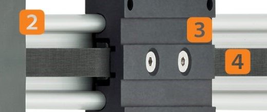
Lay the guide trough out on the machine or on the ground exactly where it will be used. Before the chain is installed, the trough must be adjusted to match the width of the chain. The width must be set so that the chain has the correct gap on each side, which should be roughly 2 millimeters on each side. Too much gap can cause the chain to slide side to side, creating wear and clacking noises. No gap, however, can create excessive wear on the side links. Some installers make a spacer block to get it right.
The trough must be level and straight. A diagonal trough will cause plastic chain links to wear or break. The trough typically rests on C‑channels. Installation kits include parts that must be attached every 2 metres. The trough should be assembled loosely at first for fine tuning and alignment. Some installers use wire or laser tools to keep the run straight. Once aligned, everything should be tightened down.
Brackets: fixed end
The fixed end (stationary end) bracket is placed near the glide bar with almost no gap. Center‑mounting is used for long strokes. For a standard center mount application, the chain glides on itself in one direction for half the stroke, then ride on glide bars in the other direction for the other half of the stroke.
With a 100‑foot stroke, placing the fixed end in the center reduces the required chain length to roughly 50 feet plus bend radius or curve. If the fixed end were placed at the far end, the full 100‑foot length would be needed (also plus bend radius). This setup only works if the trough and mounting locations are set correctly.
Brackets: moving end
For long gliding systems, the moving end would require a lowered mounting height (LMH). A specified link is reversed to allow for an S-shape. This keeps the moving end low, bringing it down lower for easier gliding motion. The moving end is typically labeled and should arrive ready to use. Once the fixed and moving ends are set, cables can be pulled through if required, though laying them directly in place by opening crossbars is usually easier.
Strain relief for gliding applications
Only the lower run of the bracket should be used when bolting the strain relief to the plate. Running bolts through the top holes is a common mistake and breaks brackets. The upper holes provide mounting options but are not intended to serve as the mounting point. Some installers try to run a long bolt through the entire bracket from the top, but this is incorrect. The bolts must go through the lower section so that the assembly mounts tightly and safely. The metal bushings in the upper section of the bracket are typically removed to prevent a catch surface for the chain.
Testing
Once everything is assembled, the system is run slowly to verify movement. If there is trough involved and if full warranty coverage is required, installers often request professional assistance. Learn more at our Orange Service page.
Questions? Reach out to us for assistance.
We are available:
- Toll-free at 1-800-965-2496 from Monday to Friday, 8am to 5pm ET
- Via live chat with our inside technical reps at www.igus.ca (same hours as above)
- Via in-person meeting with your local territory sales manager (arrange via phone or live chat)
- By appointment online with one of our product specialists: book here
We look forward to connecting with you.
If you’d like to learn more:
Energy Chain System Installation Guide: https://blog.igus.ca/2024/09/23/e-chain-assembly-instructions/
E4.1 Assembly YouTube Video: https://www.youtube.com/watch?v=Ft0YevD1M6Q
E2.1 Assembly YouTube Video: https://www.youtube.com/watch?v=opqGoOn_S1o